| Rules and Regulations | - Typical combinations
- Low-voltage switching devices (LTAs)
- Behavioral testing
- Behavior test in case of internal accidents
(localization capability) - Earthquake resistance
| - IEC 60439-1, DIN EN 60439-1, (VDE 0660 часть 500)
- IEC 61641, VDE 0660 часть 500
- IEC 60068-3-3, IEC 60068-2-57,
- IEC 60980, KTA 2201/4
|
| Air gaps and leakage distances | - Rated impulse withstand voltage (Uimp)
- Overvoltage category
- Degree of contamination
| |
| Rated insulation voltage (Ui) | | 1000V |
| Rated operating voltage (Ue) | | Up to 690V |
Rated current (In)
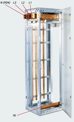
Busbars (3- and 4-pole) | Main horizontal busbars | Rated current up to 7400A
Rated withstand pulse current (Ipk) up to 375kA
Rated short-time withstand current (Icw) up to 150kA, 1s up to 120kA, 3s |
| | Vertical busbars for circuit breakers | Rated current up to 6300A
Rated withstand pulse current (Ipk) up to 250kA
Rated short-time withstand current (Icw) up to 80kA, 3s; up to 100kA, 1s |
| | Vertical busbars for rigid structure | Rated current up to 1400A
Rated withstand pulse current (Ipk) up to 163kA
Rated short-time withstand current (Icw) up to 65kA*, 1s; up to 50kA, 3s |
| | Vertical busbars for plug-in units | Rated current up to 1200A
Rated withstand pulse current (Ipk) up to 163kA
Rated short-time withstand current (Icw) up to 65kA*, 1s; up to 50kA, 3s |
| | Vertical busbars for withdrawable assembly | Rated current up to 1200A
Rated withstand pulse current (Ipk) up to 163kA
Rated short-time withstand current (Icw) up to 65kA*, 1s
Up to 50kA, 3s |
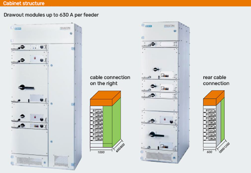
| Design currents of apparatuses | | Circuit breakers up to 6300A
Outgoing feeders up to 630A |
| Internal division | From Form 1 to Form 4 | IEC 60439-1, Section 7.7, DIN EN 60439-1 |
| Exterior surface treatment | frame, casing, doors | Galvanizing / powder coating / wet painting
Zinc plating / powder coating / wet paint
Powder coating / wet painting |
| Protection level | To IEC 60529, EN 60529 | IP 30 to IP 54 |
| Dimensions | | - 2200, 2600mm (with optional top compartment)
- 400, 600, 800, 1000, 1200mm
- 600, 800, 1000, 1200mm
|
| *Conditional rated | short-circuit current Icc up to | 100 kA |